


Since the beginning of 2018, Agile Magnetics has made a serious step in confirming its position as a leader in custom original equipment manufacturer (OEM) magnetics with the purchase of specialized FEM 3D software for analysis of electromagnetic and thermal fields.
Аs is well known, winding losses in transformers and inductors increase dramatically with frequency due to eddy-current and proximity effects. One of the most commonly used practical ways to reduce these losses is the use of Litz wire.
Using Litz wire in effectively is not as easy as it appears. Simple approaches, such as tables of recommended strand diameter by frequency, in some cases can lead to higher resistance than a simple solid-wire or foil winding, and almost always leads to higher cost and than could be achieved with more careful design.
By this reason in design of HF power magnetics, there is a need for an accurate prediction of the AC proximity and eddy current losses over a wide frequency range and for various winding geometries in the design stage when Litz wire was used.
Analytical calculation of these losses is difficult and inaccurate. The most accurate calculation can be made using Finite Element Method (FEM).
Knowing the effectiveness of FEM in determining the above said losses while designing the HF power magnetics, we at Agile magnetics use Finite Element Analysis (FEA) to simulate the electromagnetic field.
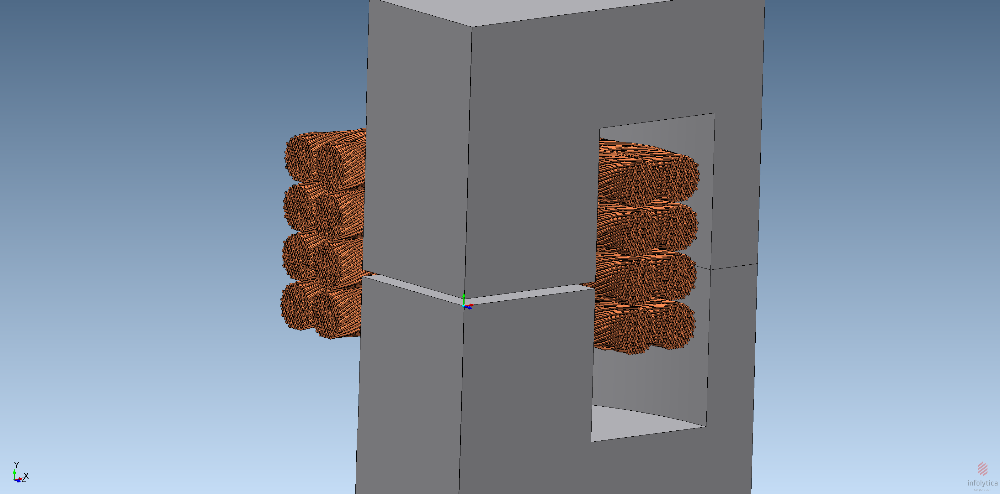
With purchased 3D FEA software, and enhancements we have added related to the construction of the Litz wire, we can virtually prototype electromagnetic devices, with respect to the complex 3D geometry of the ferromagnetic core and Litz wire windings, as example of HF gapped core inductor, shown on Fig.1
 Fig. 1 3D FEM model of HF gapped core inductor
In particular, this software enables optimal selection and construction of the core, winding configuration, and Litz wire. FЕА allows us to simultaneously determine the eddy currents, proximity and DC resistance losses in Litz wire coils depending on the electromagnetic field (Fig.2) in the design.

Fig. 2 Distribution of current density in the HF inductor model from Fig. 1
In modelling and analysis of Litz wire coils we use the most advanced techniques, including even modelling the twisting of individual strands, as was shown on Fig.1.
When the number of strands in Litz wire is very large (on the order of thousands), the modeling of each of them leads to many “heavy” FEM models, very time consuming in both the modelling, and computation stages.
Secondly, a numerical solution of such models provides information about the losses in one design but does not directly provide information on how to optimize the design. Because the Litz wire user can choose from a vast array of strand sizes and numbers of strands, it is difficult to locate a good design simply by trying different possibilities.
In such case we have added special approximation methods to evaluate the design of our power magnetics. Such approximations, used in 2D and 3D models are shown on Fig.3.

a)

b)

c)
Fig.3. Approximations for FEM models of Litz wire coils: a) 3D block modeling in Infolytica Magnet for HF inductor; b) individual Litz wire turns modeling for HF inductor; c) 2D magnetic flux distribution for a model of HF transformer with Litz wire coils in FEMM
Table 1 shows a comparison for calculated values of AC losses in HF inductor, shown on Fig.1, when different modelling techniques were used.
| No. | Modeling approach of Litz Wire coil | Ac losses, Watts |
| 1 | Block modeling (Fig. 3, a) | 0.0382 |
| 2 | Individual Litz wire turns modeling (Fig. 3, b) | 0.0589 |
| 3 | Twisted Litz wire strands modeling (Fig. 1) | 0.0526 |
It can be seen from Table 1 that the methods for approximation used in our modeling gives very good engineering accuracy in calculating the AC losses in Litz wire coils.
The FEA software allows us perform optimization of the shape of Litz wire coils with respect to the AC losses caused by the leakage field near the air gap (Fig.2) thanks to the ability to easily and quickly change the geometry in our modeling.
Parallel with shape optimization of Litz wire coils we have possibility for simulation of different type Litz wire, used in these coils, as was shown on Fig.4.

a)

b)
Fig.4. Current density distribution in different Litz wire types: a) type 1; type 2
Since solving the problems related to researching and modelling electromagnetic processes in HF power magnetics with Litz wire coils is an ongoing effort in our industry, we at Agile Magnetics constantly review new scientific research in this field, and implement the latest findings in our products.
Thanks to our highly qualified R&D experts, specialized FEA software and high-performance computer equipment, we at Agile Magnetics have the opportunity to quickly and quantitatively find solutions to our customers’ problems concerning the design of HF power magnetics with Litz wire coils.
Solutions From Agile
Agile Magnetics is a global leader in custom OEM magnetics, offering delivery reliability and extraordinary repeatability of manufacture. Our expert staff is on hand to quickly respond to inquiries and orders.
We’re proud to offer a diverse selection of both standard and custom high-performance litz wire transformers; we design and manufacture flyback bias, forward converter, gate drive, and universal winding transformers, as well as LLC and PFC chokes, with various types of this versatile wire.
To learn more about litz wire magnetics components from Agile Magnetics or discuss how we can help with your project, request a quote or design consultation today.
Comments are closed